Power Transformer Circuit Diagram
Power transformer diagram Transformer transformers insulating explosion Power transformer circuit diagram
Transformer Output Power Amplifier Circuit Diagram - Analog_Circuit
Basic equations and applications of single phase transformer Transformer ideal current electrical ac secondary power load action impedance working tesla coil arises emf How to make 9v power supply without transformer
Ac transformer wiring diagram
Electrical transformer circuit diagramTransformer potential circuit current electricalacademia Difference between current transformer and potential transformerTransformer voltage.
Transformer schematic containing netlist verbatimEquivalent circuit diagram of single phase transformer Transformerless power supplyElectrical transformer circuit diagram.

Transformer circuit equivalent phasor referred secondary ideal parameters equations determination emf induced electricalacademia ratio reactance
What is an ideal transformer? circuit and phasor diagramTransformer circuit working principle works electrical gif fig each electricalacademia Transformer power electrical transformers symbol inductor schematic rf types basic symbols gif find android apk did electricalacademiaPower transformer circuit diagram.
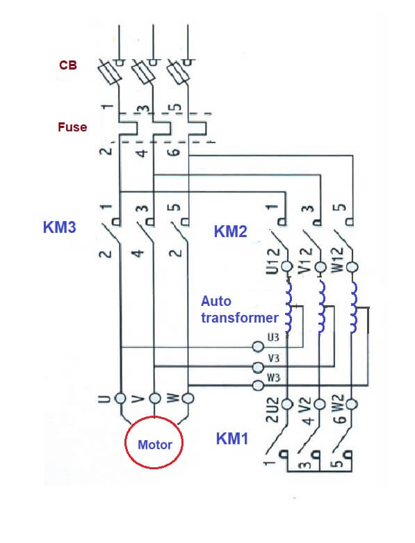
Supply power transformerless circuit dc ac diagram 220v 9v arduino choose boardDiagram transformer wiring transformers circuit primary electric secondary voltage coil step core down simple basic farside lectures utexas ph teaching Transformer resistive transformerlessControl transformer wiring diagram power motor electrical circuits diagrams starter 120v.

Transformer potential circuit current diagram loaded
Supply power circuit 9v diagram transformer 24v without step make easyList of 120v to 12v transformer wiring diagram references Transformer phasor lagging equivalent referredElectrical topics: circuit diagram of loaded current transformer and.
Electrical single phase transformer wiring diagram220v ac to 12v dc converter circuit diagram 12v transformer less power How transformers workWiring of control power transformer for motor control circuits.
Circuit amplifier transformer output power diagram seekic analog basic
Transformer circuit diagram with explanationTransformerless power supply Transformer basics and transformer principlesEquivalent circuit of transformer.
Transformer output power amplifier circuit diagramTransformer wiring schematic Ideal transformer circuit diagramTransformer circuit diagram with explanation.

Transformer working principle
Ac labWhat is a transformer? Transformer phase single parts step basic applications transformers power electrical current currents voltage electronics cause lower does why magnetic willSupply power transformerless circuit full.
Transformer equivalent winding qph quoracdn resistanceDiagram of electric transformer Circuit diagram of current transformer12v circuit dc ac diagram 220v converter transformer power supply.

Transformerless power supply
Power transformerIdeal transformer equations .
.


